GNSS interference is no longer simply an emerging concern for aerospace and defense. It is an increasingly important consideration for any application that relies on positioning, navigation or timing (PNT), from aircraft and autonomous platforms to transportation, communications infrastructure and other mission-critical systems.
For RF, antenna and GNSS hardware engineers, this raises an important design question: How can a system maintain reliable GNSS reception when an interfering signal operates within the same frequency band as the satellites?
One approach is a Controlled Reception Pattern Antenna (CRPA) system.
Unlike conventional filtering, which separates signals primarily by frequency, CRPA systems use spatial information. By combining multiple antenna elements with a multi-channel RF front end and adaptive signal processing, the system can reduce sensitivity toward the direction of an interferer while maintaining useful reception across the rest of the visible sky.
Strength in Numbers
A conventional GNSS antenna typically uses a single antenna element with a largely fixed reception pattern. It receives signals from satellites across the visible sky, but it may also receive interference occupying the same GNSS frequency bands.
Filtering can provide important protection against signals outside the required GNSS bands. However, when an interferer falls within the GNSS band itself, frequency filtering alone cannot remove it without also affecting wanted GNSS signals. This is where a CRPA architecture becomes valuable.
A complete CRPA system uses a multi-element antenna array together with independent RF channels and adaptive processing to support:
- Adaptive reception-pattern control to preserve useful GNSS reception.
- Null steering to reduce sensitivity toward interference arriving from particular directions.
- Spatial discrimination that can also help reduce sensitivity to some unwanted reflected signals.
Each antenna element feeds an independent RF channel. The CRPA processor applies complex amplitude and phase weights to the individual channels before combining them. By adjusting those weights, the system controls the resulting reception pattern according to the RF environment.
The antenna is therefore only one part of the solution. Array geometry, element performance, RF-channel matching, calibration and signal processing all contribute to overall CRPA performance.
Why the Number of Antenna Elements Matters
One of the first considerations when designing a CRPA is the number of antenna elements.
For a conventional narrowband spatial-nulling problem with one constraint used to preserve the desired response, an N-element array can theoretically provide up to N−1 remaining spatial degrees of freedom for interference suppression.
A four-element array can therefore offer up to three remaining spatial degrees of freedom in this idealized case. This is an upper bound, not a guarantee that any four-element implementation will suppress three arbitrary jammers.
Several factors determine what can be achieved in practice:
- Interference sources must be sufficiently distinguishable spatially.
- Wideband interference can require additional processing, such as space-time adaptive processing.
- Channel amplitude, phase and group-delay mismatch reduce achievable null depth.
- Mutual coupling between antenna elements changes the embedded array response.
- RF front-end and receiver dynamic range can limit suppression performance.
- Reflections can cause one interference source to appear to arrive from multiple directions.
- A null toward an interferer can also attenuate satellites close to the same direction.
Geometry and Element Spacing Matter
The number of antenna elements is only one part of CRPA design. Where those elements are positioned relative to one another is equally important.
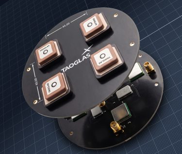
Taoglas has evaluated different four-element configurations and PCB sizes as part of the CRPA reference-design development. The physical layouts illustrate how array geometry, aperture and element separation can change according to the available platform size and RF design objectives.
| PCB diameter | Array layout | Horizontal C-C dimension | Vertical C-C dimension |
| 110 mm | 2×2 | 44 mm | 40 mm |
| 150 mm | Cross | 110 mm opposing-element separation | 110 mm opposing-element separation |
| 170 mm | 2×2 | 104 mm | 70 mm |
Table 1. Four-element CRPA PCB geometries and centre-to-centre dimensions.
PCB diameter alone does not define array aperture or element spacing. Element positions must be considered together with antenna dimensions, operating wavelength, ground-plane behavior, mutual coupling, isolation and the requirements of the overall CRPA architecture.
A larger PCB therefore does not necessarily mean greater spacing between every pair of antenna elements. Geometry and positioning can be optimized differently according to the objectives of each implementation.
Wavelength Versus Physical Spacing
The relationship between element position and wavelength becomes particularly important in a multiband GNSS array.
| GNSS band | Frequency | Free-space wavelength | Half-wavelength |
| L1 / E1 / B1C | 1575.42 MHz | 190.3 mm | 95.1 mm |
| L2 | 1227.60 MHz | 244.2 mm | 122.1 mm |
| L5 / E5a / B2a | 1176.45 MHz | 254.8 mm | 127.4 mm |
Table 2. Approximate free-space wavelength and half-wavelength for selected GNSS bands.
The compact 110 mm PCB uses approximately 44 mm × 40 mm centre-to-centre dimensions, substantially less than half a free-space wavelength across L1, L2 and L5. This supports a smaller physical implementation, but close spacing can increase mutual coupling and reduce the spatial diversity available between channels.
The 150 mm cross configuration provides 110 mm centre-to-centre separation between opposing elements across the two principal axes. Because this is the aperture between opposing elements rather than conventional nearest-neighbor spacing in a uniform array, it should not be compared directly with the common half-wavelength spacing guideline.
The 170 mm PCB uses a 104 mm × 70 mm 2×2 arrangement, further demonstrating that overall PCB diameter does not directly determine antenna-element separation.
In regularly spaced arrays, large element spacing can introduce grating lobes or directional ambiguities depending on wavelength, geometry and the angular region of operation. Conversely, very close spacing can increase mutual coupling and reduce the spatial information available between channels.
For a multiband CRPA, the challenge is greater because the electrical spacing between elements changes significantly across L1, L2 and L5. There is therefore no single physical spacing that is optimum for every GNSS band and application. The array, ground plane, RF channels, antennas and processing architecture must be considered as one system.
The RF Front End Is Part of the CRPA Architecture
Spatial processing primarily addresses interference that occupies the same frequency space as wanted GNSS signals. Out-of-band interference requires another layer of protection.
In a CRPA architecture, each antenna element has its own RF signal path. Filtering can increase rejection of unwanted out-of-band energy, while low-noise amplification and carefully controlled RF paths preserve the individual channels required by downstream processing.
The final level of protection depends on filter performance, interference power, filter placement, RF linearity and dynamic range. Filtering should therefore be treated as complementary to spatial processing rather than as a guaranteed solution to every out-of-band interference condition.
Effective multi-channel operation requires attention to:
- Filter characteristics and insertion loss.
- LNA noise figure, gain, linearity and compression behavior.
- Channel-to-channel amplitude matching.
- Phase and group-delay stability and characterization.
- Element isolation and mutual coupling.
- RF path consistency and calibration accuracy.
- Phase-center behavior across frequency and angle.
The antenna array and RF electronics therefore should not be developed independently.
A Note on Spoofing
The spatial information available from an antenna array may also contribute to more advanced spoofing-detection architectures. However, spoofing detection requires additional receiver and signal-processing capabilities and is outside the scope of the Taoglas CRPA antenna and RF reference platform described here.
Designing for GNSS Resilience
There is no single CRPA architecture that is optimum for every platform.
The appropriate design depends on the GNSS bands being supported, the physical space available, the interference environment, array geometry, antenna performance, isolation, calibration accuracy, RF-channel matching and the capabilities of the associated processing platform.
That is why evaluating CRPA performance requires looking beyond individual antenna datasheets. The antenna elements, array geometry, RF front end, calibration and processor ultimately have to operate as one system.
By addressing these factors together, engineers can develop GNSS architectures capable of adapting their reception patterns to challenging RF environments, maintaining useful satellite reception while reducing sensitivity toward interference.
For platforms where reliable positioning, navigation and timing are critical, that spatial dimension provides an important additional layer of resilience beyond conventional GNSS antenna and filtering techniques.


