A Controlled Reception Pattern Antenna (CRPA) system is an effective way to mitigate GNSS jamming attacks that use in-band signals to overwhelm legitimate ones. Unlike conventional filtering, which separates signals primarily by frequency, CRPA systems use spatial information.
By combining multiple antenna elements with a multi-channel RF front end and adaptive signal processing, the system can reduce sensitivity toward the direction of an interferer while maintaining useful reception across the rest of the visible sky. (For a deep dive, see “Inside the Array: How CRPA Systems Mitigate GNSS Jamming.”)
For hardware engineers, a key design consideration is sizing the GNSS array so it fits within the board space, weight, and L5 performance constraints. This is challenging because board size creates a trade-off between L5 efficiency, coupling, and phase-center stability against size and weight.
Why L5 is Ideal
L5 is a modernized signal designed to provide high accuracy and high availability, which is why so many designs now require it. L5 also uses a 10.23 Mcps chipping rate. That’s 10 times greater than L1 C/A, which means it provides greater ranging resolution and multipath resilience.
L5 is available on GPS, Galileo, and BeiDou:
- GPS’s L5 signal, at 1176.45 MHz, is the most advanced civilian signal available from GPS. It’s faster like the Precision codes at L1 and L2, and uses both a higher power and lower frequency. L5 is fully available from 24 satellites.
- Galileo’s E5 signal is divided into two signals: E5a is centered at 1176 MHz, which is co-located with GPS’s L5, while E5b is centered at 1207 MHz. Both are 20.46 MHz wide and can be used independently or together. Galileo’s E5 is intended to provide a similar function as GPS’s L5: higher precision with higher availability.
- BeiDou’s high-accuarcy B2a signal is at 1176.45 MHz.
For more information, see “How to Navigate the L1, L2, L5, E5a, E5b, and G2 Alphabet Soup of GNSS Constellations and Signals” and “Navigating the L1, L2 and L5 Band Options for GNSS.”
Small Size, Big Challenges
At 1176.45 MHz, L5 is the lowest GNSS band, which means every board is electrically smallest there. A patch element needs the ground plane area around it to radiate efficiently, but edge effects grow as the plane gets small relative to the wavelength. This is the physical reason why the 170 mm board is the preferred ground plane size.
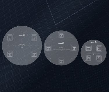
| Board | Role in the Design Work | Findings | L5 Efficiency (projected) |
| 110 mm | Learning platform | Below preferred L5 ground-plane size. High coupling and phase-center sensitivity. Identified integration limits. | ~35% |
| 150 mm | Recommended baseline | Best compact size-performance compromise. 2×2 square selected as the practical default. | 50-65% |
| 170 mm | Performance option | More spacing, lower coupling. For tighter phase-center requirements. | 65’75% |
The following analysis is based on three Taoglas antennas: the GVLB258.A stacked patch, the HP2258.A patch, and the HP25258.A stacked patch.
| Board diameter | In Wavelengths at L1 | At L2 | At L5 |
| 110 mm | 0.58 λ | 0.45 λ | 0.43 λ |
| 150 mm | 0.79 λ | 0.61 λ | 0.59 λ |
| 170 mm | 0.89 λ | 0.70 λ | 0.67 λ |
It’s important to understand how the efficiency figures translate into dB:
- 50% = -3.0 dB
- 65% = -1.9 dB
- 75% = -1.2 dB
When comparing the edges of the projected ranges, 170 mm is about 1.1 dB better at the low end (50% to 65%) and about 0.6 dB better at the high end (65% to 75%).
Antenna efficiency loss reduces signal-to-noise roughly dB for dB because it reduces the signal level the receiver sees (the antenna’s own noise contribution is a second-order effect).
| Factor | Smaller Board | Larger Board |
| L5 efficiency | Lower (projected) | Higher (projected) |
| Element spacing and coupling | Tighter, higher coupling | More spacing, lower coupling |
| Phase-center sensitivity | Higher | Lower, suits tighter requirements |
| Size and weight | Better | Worse |
| Best used for | Learning and integration limits (110 mm); compact default (150 mm) | Where maximum L5 and phase-center performance justify the size |
How to Get Started
Achieving the right isolation in a compact multi-element GNSS array starts with understanding the interactions between the antenna elements, ground plane, PCB layout, and RF architecture. Rather than treating isolation as a problem to solve after the board is laid out, consider it early in the design process and validate performance across the required GNSS bands. A design strategy that makes isolation a day-one criterion can avoid extensive, expensive rework months later when it turns out that performance doesn’t meet application requirements.
If you’re working on a compact GNSS or CRPA design, refer to the Taoglas datasheet and application note for guidance on antenna selection, placement, and integration. For additional support, consult with the Taoglas team.


